Support & Learning / Module 8 branch
Symptoms, Evidence and Diagnosis
Before this lesson: Preserve the exact symptom and stop when structure, battery, liquid or powered hardware may be unsafe.
What you will understand
- Separate the visible symptom from the functional domains that can produce it.
- Use model-specific repair experience without turning one case into a universal fault claim.
- Move from concern to written findings, approval and staged acceptance evidence.
Mini 4 Pro subsystem diagnosis
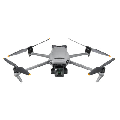
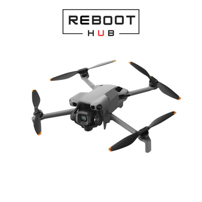
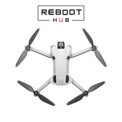
DJI Mini 4 Pro is compact, but its faults still cross distinct systems: core board processing, ESC and motors, front and rear vision, downward vision, gimbal-camera control, charging, battery communication and wireless transmission. This guide replaces old fixed-price shortcuts with a model-specific evidence path that shows what to inspect, what a symptom does not prove and what a credible repair handover should contain.
Quick answer
Map the warning to the Mini 4 Pro architecture before choosing a repair
Identify the exact aircraft, board revision, controller and battery; preserve the warning and event history; then separate power, propulsion, vision, gimbal, image, charging and link behavior. Mini 4 Pro training identifies E1E, E3T, LCPU, Charger, MCU, S2, DDR and WIFI/BT functions on the core-board architecture. Those labels guide diagnosis but do not prove which chip failed without case-level measurements.
What evidence should be captured before the customer acts?
How does repair-bench experience map the fault domains?
What does the Mini 4 Pro core-board map tell a repairer?
Model-specific training identifies E1E as a flight-control platform, E3T as a camera platform, an LCPU associated with lens STM control and temperature-compensation collection, a Charger function for USB charging, an MCU spanning flight-control, gimbal and charging business, S2 for operating and wireless-transmission functions, DDR for program and temporary data, and WIFI/BT for short-range communication. This architecture explains why main board is too broad a diagnosis.
A camera symptom, charging symptom and link symptom can live on the same physical assembly while belonging to different functional domains. The correct response is to record the exact behavior and board revision, then confirm the local finding. Reboot Hub may disclose an exact chip identifier or component result from a dated case-level repair, but that does not authorize a public board procedure or prove that the same component caused another aircraft's warning.

How should a Mini 4 Pro no-power or charging complaint be divided?
Record the exact battery, physical condition, latch, contacts, USB-C condition, supported charger and cable context, LED behavior and app warning. Determine whether the concern is no aircraft response, no charging, intermittent connection, heat, communication or one-pack behavior. The aircraft Charger function and the battery's own management are separate boundaries, so neither the pack nor the core board should be blamed from one observation.
Stop on swelling, deformation, liquid evidence, damaged terminals, odor or abnormal heat. Professional diagnosis can then separate the pack, contacts, aircraft connector, USB port, charging path and board domain. The quote states which boundary has evidence and whether the safer path is battery replacement, local connector work, component repair or a broader board scope.
What separates a Mini 4 Pro motor warning from an ESC fault?
Inspect propeller condition, motor freedom with power safely removed, debris, impact, motor mount, arm geometry, wiring and connectors. Training identifies a separate ESC board in the aircraft, but the warning path also includes motor, harness, drive components, current feedback, command and supply. Record the affected channel and compare evidence instead of assuming that the most expensive assembly failed.
A case-level board finding may name a MOSFET, driver or sensing part when measurement and board revision are documented. That finding is useful repair experience, not a universal replacement instruction. After repair, compare channels, temperature and command behavior, then progress through controlled propulsion and flight gates only when all earlier checks are safe.

How are front, rear and downward vision warnings diagnosed?
Record the exact direction, warning, lighting, surface texture, contamination, condensation and aircraft attitude. Inspect windows, module seating, brackets, harnesses and the impact path. Front and rear vision assemblies and downward vision serve different observations; a low-light or low-texture limitation is not the same as a persistent hardware fault in controlled conditions.
Calibration behavior should be interpreted after physical and connection checks, not used to hide a displaced module or damaged bracket. The written finding should state whether the evidence is environmental, mechanical, connector-related, module-level or core-board related. Acceptance should test the affected directions under documented conditions and avoid claiming that one hover proves every automated function.
What should be checked when the gimbal moves but the image fails?
Separate gimbal mechanics from camera and image processing. Observe startup without forcing an axis; inspect dampers, frame, axis freedom, ribbon routing and connectors; then record live image, focus, recording and media behavior. A centered gimbal can still have a camera or processing fault, while a black image does not prove that all axis motors or dampers need replacement.
The E3T camera domain, LCPU lens-control role, MCU gimbal functions, ribbon paths and camera assembly form different hypotheses. A professional report names the confirmed boundary and board revision where relevant. Post-repair validation should separately document stabilization, focus, image, recording and any supported mode involved in the original concern.

How is controller or transmission trouble kept separate from the aircraft?
Identify the controller, pairing state, antennas, cable or display context, firmware relationship and location. Distinguish failure to pair, intermittent control, telemetry loss, image breakup and app behavior. Record whether the problem follows one controller, one site, one orientation or one aircraft state. Do not treat advertised range as a repair test or a guarantee.
S2 and related wireless functions on the architecture help locate the domain, but antennas, connectors, power stability, controller and environment remain separate. A returned aircraft should demonstrate stable supported pairing, controls, telemetry and image under stated conditions. If interference or intermittent behavior could not be reproduced, that unknown stays in the written handover.
What evidence matters after a Mini 4 Pro impact or liquid event?
Preserve the event and avoid repeated power cycles when liquid or serious impact is suspected. Inspect shell, arms, motor mounts, gimbal supports, battery bay, connectors, harnesses and visible indicators. Compact construction can transmit force across assemblies, and moisture can reach connections beyond the visible entry point. A clean exterior or startup does not clear hidden risk.
The diagnosis should separate confirmed damage, credible adjacent risk and inaccessible areas. Localized connector or component work may be appropriate when the damage is bounded; structural, corrosion or multi-domain damage may make assembly replacement stronger. Reboot Hub gives the customer that known and unknown boundary before approval, together with the proposed tests.

What belongs in a Mini 4 Pro post-repair test?
Model-specific training uses linked tests rather than a single power-on: hardware connections, multidirectional gimbal and motor behavior, controller pairing, warnings, image and recording, compass and IMU functions, battery assessment and controlled flight. The exact sequence depends on the work and safety condition, but the principle is constant: address the original symptom and adjacent systems affected by access or replacement.
The handover records the exact aircraft, work, part provenance, tests and remaining observations. It also distinguishes service time from shipping and separates a repair warranty from a product warranty. That evidence lets the customer choose repair, replacement or further observation without relying on an old fixed-price table or dramatic top-failure claim.
Keep exploring
Further reading
From The Reboot Hub Chronicle


From Drone Guides