Support & Learning / Module 8 branch
Symptoms, Evidence and Diagnosis
Before this lesson: Preserve the exact symptom and stop when structure, battery, liquid or powered hardware may be unsafe.
What you will understand
- Separate the visible symptom from the functional domains that can produce it.
- Use model-specific repair experience without turning one case into a universal fault claim.
- Move from concern to written findings, approval and staged acceptance evidence.
Mavic 3 model-specific repair path
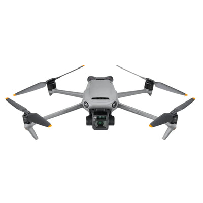
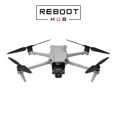
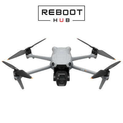
A Mavic 3 warning is a symptom, not a parts list. The aircraft combines a core board, separate power and propulsion paths, positioning and inertial sensing, multidirectional vision, gimbal-camera systems and a radio link. This guide shows how to preserve evidence, isolate the affected domain and decide between component repair, assembly replacement and a documented replacement aircraft.
Quick answer
Confirm the Mavic 3 variant and symptom boundary before ordering parts
Record whether the aircraft is Mavic 3, Mavic 3 Cine, Mavic 3 Classic or another family variant, then capture the exact warning, event history, controller, battery, camera behavior and affected functions. Test from safe external evidence toward controlled subsystem checks. Reboot Hub provides written findings and known and unknown items before approval instead of attaching a fixed price or universal component diagnosis to a warning.
DJI Mavic 3 · series repair estimates by path
Each USD figure is a historical series-level estimate for the listed repair path, not a quote for this exact aircraft. Diagnosis determines the parts, labor, calibration, and testing needed.
| Repair path | Estimated USD range | When to consider it |
|---|---|---|
| Ribbon / flex cable | $60-$96 | Camera signal, gimbal tilt, image loss, or impact-damaged cable routing. |
| Complete gimbal module | $240-$336 | Camera, lens, motor, or stabilization damage beyond a cable-only repair. |
| ESC module / board | $84-$108 | Propulsion warnings, motor-control faults, water exposure, or ESC-stage damage. |
| Motor arm replacement | $72-$96 | Structural damage involving an arm, hinge, landing point, shell, or motor mount. |
| Main board (chip-level) | $180-$216 | A board fault can be isolated at component level before full-board replacement. |
| Complete board replacement | $360 | The board is physically unrecoverable or component-level repair is not practical. |
| IMU sensor / calibration path | $60 | Calibration loops, drift, sensor errors, or unstable attitude require diagnosis. |
| Battery management board | $72-$96 | Charging, balancing, BMS, or battery power-path faults require diagnosis. |
What evidence should be captured before the customer acts?
How does repair-bench experience map the fault domains?
Which Mavic 3 variant and kit are on the bench?
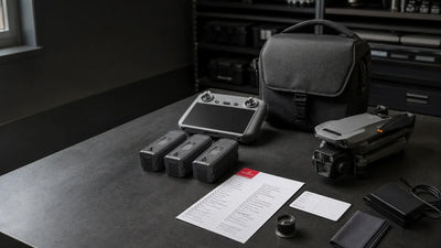
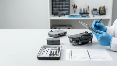
Read the aircraft identity and record the camera configuration, internal-storage context where relevant, controller model, batteries, charger, filters and supplied accessories. Similar names do not make every gimbal, camera, board or controller interchangeable. Photograph the aircraft, gimbal, arm roots, battery bay, ports and kit before work. If the seller or owner reports earlier repair, ask what assembly was changed and whether any calibration or pairing followed.
The intake establishes a durable evidence boundary. A dated case can name a chip, connector, MOSFET or measured rail when the exact model and board revision are recorded. That repair experience is valuable and may be published, but it cannot become a universal instruction for every Mavic 3 warning. Unknown provenance or missing history belongs in the written findings rather than being filled with a confident assumption.
How is a Mavic 3 no-power complaint investigated?
Start with pack identity, physical condition, latch, terminals, charger history and supported app evidence. Record whether the aircraft is fully unresponsive, restarts, heats abnormally or fails only with one pack. The core board cannot be blamed until battery input, connectors, harnesses and relevant regulated power domains are separated. Stop any evaluation when there is swelling, deformation, liquid evidence, burnt odor or abnormal heat.
Power diagnosis should progress under controlled service conditions and remain non-procedural in public content. The customer needs the confirmed boundary: battery replacement, connector work, local component repair, core-board repair or unresolved intermittent behavior. The quote should also explain whether data, pairing, calibration or adjacent systems require validation after the approved work.
What separates a motor problem from an ESC problem?
Inspect propellers, motor movement with power safely removed, shaft and mount condition, arm geometry, wiring and connectors. Record which channel reports the warning and whether impact or debris is present. The ESC domain includes drive components, control, current feedback and supply behavior, while the motor and harness remain separate. A stopped motor does not, by itself, identify a shorted power component.
Repair experience may confirm a specific MOSFET, driver or sensing component on one board revision. Publish that as a case-level finding with the model, symptom and validation context, not as an instruction to replace the same part on every aircraft. Post-repair acceptance compares channels, observes temperature and command behavior, then advances to controlled propulsion and flight checks only after safe ground gates pass.

How should GPS, IMU and compass warnings be separated?
Record the site, sky view, nearby metal or electrical equipment, warning wording, heading behavior and whether the issue followed impact, storage, repair or update. GPS, compass and IMU serve different roles even when the app presents a combined flight-readiness problem. Inspect relevant modules, mounts, connectors and frame alignment before interpreting calibration behavior. A request to calibrate is evidence, not proof that calibration is the cause.
Model-specific repair material shows GPS and IMU as distinct functional boundaries connected to the wider aircraft. A core-board defect can affect navigation reporting, but so can a local module, harness, impact path or environment. The written diagnosis should say which domain was confirmed and which was excluded. Return-to-flight testing should verify consistent inertial and positioning behavior in an appropriate controlled setting.
What does a vision-system warning really tell you?
Determine the affected direction and record illumination, surface texture, contamination, condensation and aircraft attitude. Inspect sensor windows, brackets, alignment, harnesses and surrounding shell damage. A warning that appears only in unsuitable light or over a low-texture surface differs from a fault that persists in controlled conditions. Impact can disturb alignment while leaving the outer window apparently intact.
Do not promise that one calibration or short hover proves the complete vision system. The repair record should state whether the finding was environmental, mechanical, connection-related, module-level or board-related. Acceptance should include supported ground checks and staged observations of the affected directions, with the tested conditions made explicit for the customer.
How are gimbal mechanics, camera electronics and image faults divided?
Observe startup without forcing an axis. Inspect dampers, frame, covers, axis freedom, ribbon routing and connectors, then record stabilization, live image, focus, recording and storage behavior. A gimbal that moves can still have image, focus or recording faults; a black image can occur with a mechanically centered gimbal. Likewise, a calibration warning can arise from obstruction, alignment, feedback, communication or prior assembly work.
A strong quote names the failed boundary and the evidence: mechanical correction, ribbon or connector repair, camera assembly, gimbal control, board work or an unresolved intermittent condition. If a case-level component is confirmed, include the board revision and post-repair tests. The customer should know whether image, stabilization and recording were each verified rather than receiving the vague statement that the camera works.
How is O3-class link evidence kept separate from site interference?
Identify the controller, pairing state, antennas, cable or display context, firmware relationship and location. Separate failure to pair, control interruption, telemetry loss, image breakup and recording issues. Reproduce the concern in an appropriate controlled environment without treating published range as a repair target. Record whether the symptom follows one controller, location, orientation or aircraft state.
A component conclusion requires more than a weak signal report. Antenna paths, connectors, radio assemblies, power stability and core processing can overlap, while the environment remains a competing explanation. The handover should show stable pairing, telemetry, controls and image under the tested conditions and disclose what was not reproduced. That is more credible than an absolute range guarantee.
What changes after impact or liquid exposure?
Preserve the event history and do not power-cycle a wet or visibly damaged aircraft to see whether it survived. Inspect force paths through shell, arms, motor mounts, gimbal supports, connectors and board areas. Liquid evidence can travel beyond the visible entry point and may create delayed corrosion. A clean exterior or successful startup does not erase those risks.
The scope should distinguish immediate confirmed damage, credible adjacent risk and inaccessible areas. A localized repair may be appropriate when damage is bounded and the board remains structurally sound; broader substrate, multi-domain or corrosion damage may favor assembly replacement. The customer receives that uncertainty in writing before approval, not after a second failure.
What should a Mavic 3 post-repair gate prove?
Match the returned aircraft and kit to intake, then address the original concern and adjacent systems touched by access or impact. Check supported firmware and pairing context, warnings, battery behavior, hardware links, gimbal and image, recording, GPS, compass, IMU, vision, propulsion observations and controlled flight when appropriate. A single power-on or hover is only one stage.
Reboot Hub records the test boundary, result, parts provenance and remaining observations. The owner can compare the approved repair with a documented replacement route when downtime, multi-system damage or uncertainty makes replacement stronger. The result is a transparent decision from the customer's concern to written findings and return-to-service evidence.
Keep exploring
Further reading
From The Reboot Hub Chronicle


From Drone Guides