Support & Learning / Module 8 branch
Symptoms, Evidence and Diagnosis
Before this lesson: Preserve the exact symptom and stop when structure, battery or powered propulsion may be unsafe.
What you will understand
- Separate the visible symptom from the system domains that can produce it.
- Understand which repair-bench observations support a conclusion and which remain hypotheses.
- Move from concern to written findings, approval and staged return-to-service evidence.
Mini 4 Pro diagnosis grounded in model-specific repair architecture
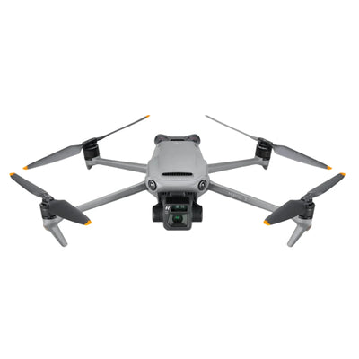
DJI Mini 4 Pro complaints often cluster around gimbal behavior, vision sensing, battery or charging, propulsion and USB communication. The model's repair training shows these functions span separate assemblies and processors, so one visible warning should not be turned into one universal part diagnosis.
Quick answer
Route the symptom through the exact Mini 4 Pro system before choosing a part
Preserve the warning and event context, inspect physical and connection evidence, identify the relevant core board, ESC board, vision assembly, gimbal or battery path, then require a written finding and model-specific post-repair test. Avoid unsupported DIY board or battery procedures.
What evidence should be captured before the customer acts?
How does repair-bench experience map the fault domains?
What does the Mini 4 Pro architecture change about diagnosis?
Model-specific repair training identifies a core board assembly, separate ESC board, front-and-rear vision assembly, downward vision assembly, camera-and-gimbal assembly and defined battery paths. The core board itself divides work across E1E, E3T, LCPU, Charger, MCU, S2, DDR and WIFI/BT functions. This makes a single 'main board fault' label too vague for a useful quote.
Architecture is not a public soldering map. It helps connect the owner's symptom to a system boundary and shows what must be tested after work. An exact chip, component or price can be published when tied to the correct board revision and dated case-level evidence, but it cannot be generalized across every Mini 4 Pro with a similar warning.

How should a limp, tilted or overloaded gimbal be routed?
Record startup movement, image output, axis behavior, impact or debris history and the exact app warning. Inspect dampers, physical alignment, visible cable condition and free movement without forcing the mechanism. A limp gimbal can involve an axis motor, feedback, cable, camera assembly, control or connection; a calibration result alone cannot identify which.
The Mini 4 Pro training flow separates image problems from motion problems, then checks image quality, mechanical movement and supported calibration. A repair should name the confirmed branch and preserve the original camera and calibration data where practical. Post-repair evidence must include image, recording, axis behavior and controlled movement.
How are front, rear and downward vision faults separated?
Record the affected direction, environment, lighting, surface, lens condition and warning. The training materials identify distinct front-and-rear and downward vision assemblies and their connections to the core board. A dirty lens, bracket or cable issue, calibration dependency, assembly fault and core-board relationship can produce different versions of 'vision unavailable.'
Test in a suitable environment and use supported calibration only after physical condition and connection evidence are credible. If the warning persists, stop relying on the affected assistance function. The written scope should state whether work involves cleaning and alignment, a vision assembly, cable or core-board diagnosis and which directional tests will close the repair.

What does a Mini 4 Pro battery or charging complaint prove?
Very little by itself. Identify the exact pack, inspect water or opening evidence, latch, contacts and shape, then record LED, app and charging behavior. The training flow separates no response, firmware-update state, charging-circuit behavior, communication and cell-condition evidence. Do not deep-discharge, open or rewrite a pack to clear a warning.
The aircraft core board includes a Charger function for USB charging, while the pack has its own management and protection. A failure can therefore sit in the pack, contacts, aircraft connector, USB port, charger path, core board or firmware relationship. The quote should identify which boundary has evidence and whether the safer choice is pack replacement or aircraft repair.
How should a motor warning be investigated?
Check propellers, motor movement with power safely removed, impact, debris, motor wiring, connector condition, battery context and the affected channel. Mini 4 Pro training identifies the ESC board as a separate assembly mounted in the frame and connected to the core board. That structure helps separate a motor fault, wiring fault, ESC drive issue and command-path issue.
A board-revision case may show a specific MOSFET, sensing or control component failure. That exact case-level finding can appear in the repair record, but it should not become a public instruction to replace that chip for every warning. Post-repair testing needs channel comparison, controlled propulsion behavior, temperature observation and a staged flight gate.

How is USB-C damage separated from charging or data faults?
Inspect connector alignment, debris and physical damage, then compare a known-good supported cable and power source. Record whether the aircraft charges, connects for supported data functions or shows intermittent behavior. Do not repeatedly force a loose connector; mechanical damage can extend to pads, traces or nearby components.
The diagnostic branches include port mechanics, cable, power source, charging path, data path and core-board functions. A component-level port repair may be appropriate when local damage is bounded and the board remains sound. Broader substrate or charging damage may require a different scope. The quote should state which functions will be tested after repair.
What should a Mini 4 Pro post-repair test include?
DJI's model-specific training lays out linked tests rather than one power-on check: firmware and authentication state where applicable, hardware-link checks, multidirectional gimbal and motor behavior, controller pairing, app warnings, image and recording, compass and IMU functions, battery assessment and controlled flight. Replacement of some assemblies can also create data or calibration dependencies.
A public article should not expose service-only software or methods that defeat identity, protection or safety systems, but it can explain the acceptance logic. The returned unit should address the original symptom and adjacent systems affected by the repair. The customer receives the test boundary, result and any remaining observation in writing.

How should five symptom paths be priced?
Do not assign one static price to a symptom. A gimbal complaint may be alignment, cable, axis, camera assembly or board control; a vision complaint may be environment, bracket, cable, module or core board; a charging complaint may be port, charger path or battery. Each path changes parts, labor, calibration and testing.
Use the live repair cost database for planning and request a current written quote for the exact unit. A dated case price can be useful when the model, board revision, finding and scope are shown. Reboot Hub compares the approved repair with a documented replacement option when the total uncertainty, downtime or multi-system damage makes replacement stronger.
How does Reboot Hub turn a Mini 4 Pro warning into a decision?
We start with the customer's concern, exact aircraft, supplied kit and event history. We map the symptom to the model-specific assemblies, preserve known evidence, identify unknowns and provide written findings before approval. If a precise chip or component is confirmed on that board revision, it can be named as case-level repair experience rather than hidden behind vague language.
The customer then sees the proposed scope, provenance, tests, timing, price and written terms. This is more useful than a list of dramatic 'top failures' because it explains what action follows each symptom and what proof should exist before the aircraft returns to service.
Keep exploring
Further reading
From The Reboot Hub Chronicle











From Drone Guides